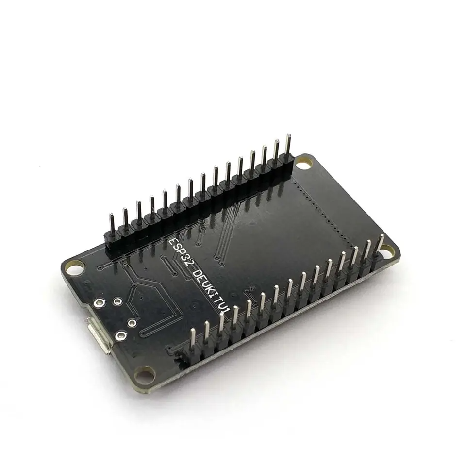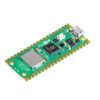
ESP32 WROOM 4Mb Devkit V1 Board with WiFi Bluetooth and Dual Core processor (OT101-B51)
Would you like to order large quantities of this product or do you need a quote to order within your organization? Then request a quote.
REQUEST QUOTEYou will receive the quote in your mailbox within a few minutes.
The ESP32 development board is ideal for IoT (Internet Of Things) projects because it has onboard WiFi and Bluetooth. Simply program via the Arduino IDE. Watch the Youtube video above for the installation of that board in the Arduino IDE.
This ESP32 module is also suitable for WLED.
Use the OTRONIC ESP32 manual to quickly get started with your ESP32 Devkit V1 board.
NOTE: This ESP32 Devkit V1 does NOT fit on a standard breadboard. The ESP32-S DOES fit on a standard breadboard.
This ESP32 board has:
18 Analog-to-Digital Converter (ADC) channels
3 SPI interfaces
3 UART interfaces
2 I2C interfaces
16 PWM output channels
2 Digital-to-Analog Converters (DAC)
2 I2S interfaces
10 Capacitive sensing GPIOs
ESP32 Wroom32 DevKit has a total of 25 GPIOs, some of which can only be used as inputs.
ESP32 voltage VIN or USB: The power supply for the ESP32 DevKit V1 is powered via the built-in Micro USB connector (5V) or directly via the "VIN" pin. The ESP32 can operate on an external power supply from 6 to 20 volts. If you use more than 12V, the voltage regulator can become very hot and will shorten its lifespan. In that case it is better to use a STEP DOWN converter to step down the voltage.
Input Only PinsGPIO 34GPIO 35GPIO 36GPIO 39Not all pins have input pullup, you need external pullup on these pins when using as input pullup.
Not all pins have an input pullup, you will need to add an external pullup resistor. Here is an overview.
Pins with internal pull up INPUT_PULLUPGPIO14GPIO16GPIO17GPIO18GPIO19GPIO21GPIO22GPIO23
Pins without internal pull upGPIO13GPIO25GPIO26GPIO27GPIO32GPIO33
The nice thing about this board is that you can use it in several ways regarding WiFi communication.
As mini access point
As WiFi client
As Web server
Peer-to-peer with ESP Now
We would like to explain the latter briefly. ESP NOW is a technology that makes it possible for modules to communicate directly with each other via their MAC address. In addition, there is also a message back whether the data has been received, which allows for a good check to be carried out whether messages arrive and you can validate this.
With ESP Now you can work very modularly and it is also extremely fast. This way you can run your program on one ESP32 while you only let other ESP32 boards respond and, as it were, be an extension of your GPIO pins.
1 ESP32 can communicate with up to 20 other boards.
A good explanation of ESP NOW by Andreas Spiess can be found here: https://www.youtube.com/watchv=6NsBN42B80Q
Delivery: Header pins already soldered. Ready to use.
Install ESP32 in Arduino IDE
To be able to program the ESP32 in the Arduino IDE, some things must first be set:
Install Arduino IDE software (www.arduino.cc)
In Arduino IDE, go to FILE and then to PREFERENCES.
Enter the following URL under MORE BOARD MANAGER URLS: https://dl.espressif.com/dl/package_esp32_index.json
Now go to UTILITIES, BOARD and BOARD MANAGEMENT
Find the correct library (ESP32 by Espressif Systems) and install it (this only needs to be done once)
Select the DOIT ESP32 Devkit V1 board in the list under UTILITIES, BOARD
Set the upload speed to 115200 baud
Set the port to the correct COM port
ESP32 does not work or does not work properly See the solutions below.
ESP32 upload code does not work or gives the message A fatal error occurred: Failed to connect to ESP32: Timed out Connecting
If you notice that nothing happens during the upload, you can briefly press the BOOT button on the ESP32 board during the upload. As soon as the upload starts you can release it. This takes some searching for the right moment.
ESP32 has no COM port in Arduino IDE
If there is no COM port available in the Arduino IDE under TOOLS -> PORT, the CP210x driver may need to be reinstalled. This is the USB chip on this board. Search on Google or download the driver here: https://www.silabs.com/developers/usb-to-uart-bridge-vcp-drivers
It could also be due to the micro USB cable, which may not be a data cable. There are many so-called charging cables in circulation that are only suitable for charging a telephone, for example. Replace the cable with a suitable micro USB data cable or order a suitable cable at otronic.nl.
ESP32 Serial monitor does not work or gives strange characters in Arduino IDE
Set the baud rate to 115200 baud in the Serial Monitor window at the bottom right.
ESP32 GPIO pins do not match the pins in the code
The GPIO pins on ESP development boards do not always match the values printed on the boards. Therefore it is important to always consult the correct PINOUT diagram. You can find this in the OTRONIC ESP32 Quick Start Guide
DimensionsLength: 5.23cmWidth: 2.82cmHeight: 1.33cm


